Monday 13 March 2017

Pendulum Type Governor

Pendulum Type Governor

Pendulum Type Governor

The governor system is like a cruise control system. It maintains the speed of your lawn mower or outdoor power products. When Briggs & Stratton governors are adjusted properly, they keep your speed steady regardless of engine load – the amount of work the engine must perform.
car speed governor, or speed limiter, is a device that sets and limits a car’s top speed. When a car that is fitted with a speed governor reaches a preset top speed, the device begins to curtail combustion and limits the supply of fuel and air to the engine.

Pendulum Type Governor:


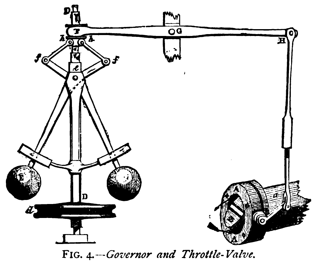
Centrifugal governors are used to balancing the rotating balls by using the centrifugal force. Two balls with equal mass are attached to the arms, they are called as fly balls or governor balls. With the help of spindle, balls rotate and the engine is driven by the bevel gear. To the spindle upper end arms are joined, when the balls are revolving about the vertical axis they move up and down.

Pendulum governor

                  Watt Governors:

Balls are arranged on the two arms and the upper arm is connected to the spindle and lower arm is connected to the sleeve. Watt governor is used in the steam engine by James watt. With the help of the output shaft the spindle is driven.

Working of Watt governor

Watt governor is the simplest and gravity controlled form of the centrifugal governors. It consists of two fly balls attached to the sleeve of negligible mass. The upper sides of arms are pivoted so that its balls can move upward and downward as they revolve with a vertical spindle. The engine drives the spindle through bevel gears. The lower arms are connected to the sleeves. The sleeve is keyed to the spindle in such a way that revolves with the spindle. At the same time, it can slide up and down according to the spindle speed. Two stoppers are provided at the bottom and top of the spindle to limit the movement sleeve.

  • In the case of watts governor, the controlling force is provided by the action of gravity, at uniform speed controlling force is equal to the centrifugal force, and it balances each other.

Pinned, Open arm and Crossed arm type Watt governor

[Describe open and crossed arm types Watt governor?]
The Watt governor is classified into three based on the position of upper arms. The arms can be connected in following three ways.
a. Pivot is on the axis of spindle
b. Pivot is offset from spindle
c. Pivot is offset, and arms cross the axis.
types_of_watt_governor
Simple pinned: The upper arms are joined to a point “O” on the axis of the spindle, where both arms intersect the spindle axis.
Open arm type: Instead of connecting directly to the spindle, the upper arm of Watt governor is hinged on a collar attached to the spindle (or joined by a horizontal link) as shown in fig b. The arms when produced meets the axis of the spindle at O.
Crossed arm type: The upper arms o governor in hinged on a collar on the axis of the spindle (or arms are joined through a fixed horizontal link) as shown in fig c. The arms intersect the axis at a point O.

Limitations of Watt governor

  • Watt governors are limited to in vertical position applications.
  • Watt governor is used in very slow speed engine. At higher speed, the sensitivity will decrease.

Limitations of Watt governor

  • Watt governors are limited to in vertical position applications.
  • Watt governor is used in very slow speed engine. At higher speed, the sensitivity will decrease.

Watt governor height equations and calculations

m = Mass of the ball, kg
w = Weight of ball, N
h = Height of the governor- the vertical distance between the center of the ball and a point O, where the arms meets the axis of the spindle, m
r = Radial distance of balls from the axis of the spindle, m
ω = Angular velocity of the balls and arms about the spindle axis, rad/s
T = Tension in the arm, N

It is assumed that the sleeve is frictionless, the weight of links/ arms is negligible. Now the ball is in equilibrium under the action of the following force
  1. Centrifugal force acting on the balls, Fc = m ω2 r
  2. The weight of balls, w = mg
  3. Tension in the upper arms, T
There is no tension in lower arms because it is assumed the sleeve is frictionless and weight of arms are negligible.
OR
Take moment of these forces about O.
For equilibrium
watt_governor_height_equation_from_momentum
Sleeve lift equal to 2 (h2 – h1)
h1 sleeve position at speed N1
h2 sleeve position at speed N2
  • The height of the ball is independent of the mass of the ball, it only depends on the speed of the spindle.
  • At higher speed, the sensitivity of watt governor will decrease.

centrifugal governor

centrifugal governor

centrifugal governor is a specific type of governor with a feedback system that controls the speed of an engine by regulating the amount of fuel (or working fluid) admitted, so as to maintain a near-constant speed, irrespective of the load or fuel-supply conditions. It uses the principle of proportional control.
It was invented in 1788 by James Watt to control his steam engine where it regulates the admission of steam into the cylinder(s). Its widest use was on steam engines during the Steam Age in the 19th century. It is also found on internal combustion engines and variously fueled turbines, and in some modern striking clocks.

How does a governor works?

The governor system is like a cruise control system. It maintains the speed of your lawn mower or outdoor power products. When Briggs & Stratton governors are adjusted properly, they keep your speed steady regardless of engine load – the amount of work the engine must perform.

What is Governor in mechanical engineering?

governor, or speed limiter, is a device used to measure and regulate the speed of a machine, such as an engine.

What does the governor do in a car?

car speed governor, or speed limiter, is a device that sets and limits a car’s top speed. When a car that is fitted with a speed governor reaches a preset top speed, the device begins to curtail combustion and limits the supply of fuel and air to the engine.

Internal combustion engine

Internal combustion engine

IC engine:

                                                 An Internal combustion engine engine (ICE) is a heat engine where the combustion of a fuel occurs with an oxidizer (usually air) in a combustion chamber that is an integral part of the working fluid flow circuit. In an internal combustion engine the expansion of the high-temperature and high-pressure gases produced by combustion applies direct force to some component of the engine. The force is applied typically to pistons, turbine blades, rotor or a nozzle. This force moves the component over a distance, transforming chemical energy into useful mechanical energy.
The term I.C engine usually refers to an engine in which combustion is intermittent, such as the more familiar four-stroke and two-stroke piston engines, along with variants, such as the six-stroke piston engine and the Wankel rotary engine. A second class of I.C engines use continuous combustion: gas turbines, jet engines and most rocket engines, each of which are internal combustion engines on the same principle as previously described. Firearms are also a form of IC engine.
Internal combustion engines are quite different from external combustion engines, such as steam or Stirling engines, in which the energy is delivered to a working fluid not consisting of, mixed with, or contaminated by combustion products. Working fluids can be air, hot water, pressurized water or even liquid sodium, heated in a boiler. ICEs are usually powered by energy-dense fuels such as gasoline or diesel, liquids derived from fossil fuels. While there are many stationary applications, most ICEs are used in mobile applications and are the dominant power supply for vehicles such as cars, aircraft, and boats.

Classification:


By number of strokes
  • Two-stroke engine
  • Clerk Cycle 1879
  • Day Cycle
  • Four-stroke engine (Otto cycle)
  • Six-stroke engine
By type of ignition
  • Compression-ignition engine
  • Spark-ignition engine (commonly found as gasoline engines)
By mechanical/thermodynamical cycle (these 2 cycles do not encompass all reciprocating engines, and are infrequently used):
  • Atkinson cycle
  • Miller cycle
Rotary:
  • Wankel engine
Continuous combustion:
  • Gas turbine
  • Jet engine
      • Rocket engine
      • Ramjet
The following jet engine types are also gas turbines types:
      • Turbojet
      • Turbofan
      • Turboprop

Reciprocating Engines:

A reciprocating engine is an engine that uses one or more pistons in order to convert pressure into rotational motion. They use the reciprocating (up-and-down) motion of the pistons to translate this energy.[1] There are many different types, including the internal combustion engine which is used in most motor vehicles, the Steam engine which is a type of external combustion engine, and the Stirling engine. These engines share common characteristics but vary extremely differently in their functioning, providing many different advantages and disadvantages.


4-stroke engines:

The top dead center (TDC) of a piston is the position where it is nearest to the valves; bottom dead center (BDC) is the opposite position where it is furthest from them. A stroke is the movement of a piston from TDC to BDC or vice versa together with the associated process. While an engine is in operation the crankshaft rotates continuously at a nearly constant speed.
    1. Intakeinduction or suction: The intake valves are open as a result of the cam lobe pressing down on the valve stem. The piston moves downward increasing the volume of the combustion chamber and allowing air to enter in the case of a CI engine or an air fuel mix in the case of SI engines that do not use direct injection. The air or air-fuel mixture is called the charge in any case.
    2. Compression: In this stroke, both valves are closed and the piston moves upward reducing the combustion chamber volume which reaches its minimum when the piston is at TDC.
    3. Power or working stroke: The pressure of the combustion gases pushes the piston downward, generating more work than it required to compress the charge.
    4. Exhaust: The exhaust valve remains open while the piston moves upward expelling the combustion gases.

2-stroke engines:

The defining characteristic of this kind of engine is that each piston completes a cycle every crankshaft revolution. The 4 processes of intake, compression, power and exhaust take place in only 2 strokes so that it is not possible to dedicate a stroke exclusively for each of them. Starting at TDC the cycle consist of:
  1. Power: While the piston is descending the combustion gases perform work on it—as in a 4-stroke engine—. The same thermodynamic considerations about the expansion apply.
  2. Scavenging: Around 75° of crankshaft rotation before BDC the exhaust valve or port opens, and blowdown occurs. Shortly thereafter the intake valve or transfer port opens. The incoming charge displaces the remaining combustion gases to the exhaust system and a part of the charge may enter the exhaust system as well. The piston reaches BDC and reverses direction. After the piston has traveled a short distance upwards into the cylinder the exhaust valve or port closes; shortly the intake valve or transfer port closes as well.
  3. Compression: With both intake and exhaust closed the piston continues moving upwards compressing the charge and performing a work on it. As in the case of a 4-stroke engine, ignition starts just before the piston reaches TDC and the same consideration on the thermodynamics of the compression on the charge.

Engine Governor

Engine Governor

Governor:

A governor, or speed limiter, is a device used to measure and regulate the speed of a machine, such as an engine.
Controlling Force is the inward radial force exerted on each ball of a centrifugal governor by the arms, spring, etc. which are attached to it. At any equilibrium speed the controlling force is equal and opposite to the centrifugal force.Effort is the mean force exerted at the sleeve due to a 1% change in the speed of the governor.Power is the work done at the sleeve for a 1% change in speed. It is called “The Power” and is equal to the effort times the sleeve displacement.Sensitivity is defined as the ratio of the mean speed to the speed range of the governor over its limits of operation.Stability: A governor is said to be stable if there is one equilibrium speed for each radius of rotation r and this speed increases with the radius. i.e.
\left ( \frac{dF}{dr}>\frac{F}{r} \right )
Isochronism: A governor is said to be isochronous if, neglecting friction, the equilibrium speed is the same for all radii of the balls. This implies infinite sensitivity and the governor will always fly to one or other extreme position.Hunting: The governor is said to hunting if the engine speed is caused to fluctuate continually above and below the mean speed. This is caused by over-compensation of the energy supply due to the governor being too sensitive.
A classic example is the centrifugal governor, also known as the Watt or fly-ball governor on a reciprocating steam engine, which uses the effect of centrifugal force on rotating weights driven by the machine output shaft to regulate its speed by altering the input flow of steam.

Types of Governors:

Inertial Governors

Centrifugal Governors

                      Pendulum Type Gov.

                                                             Watt governor

                     Loaded Type Gov.

                                          Gravity Controlled Gov.
                                                                             Porter Gov.
                                                                             Proell Gov.
                                                          Spring Controlled Gov.
                                                                              Hartnell Gov.
                                                                             Wilson Hartnell Gov.
                                                                             Hartung Gov.
                                                                              Pickering Gov.

HOW DOES A SMALL ENGINE GOVERNOR WORK?

The governor system is like a cruise control system. It maintains the speed of your lawn mower or outdoor power products. When Briggs & Stratton governors are adjusted properly, they keep your speed steady regardless of engine load – the amount of work the engine must perform.

Inertial Governors

Inertial Governors

Inertia Governor : In inertia governors, the balls are arranged in manner that the inertia forces caused by angular acceleration or retardation of the governor shaft tend to change their position.
The function of a governor is to regulate the mean speed of an engine, when there are variations in the load e.g. when the load on an engine increases, its speed decreases, therefore it becomes necessary to increase the supply of working fluid. On the other hand, when the load on the engine decreases, its speed increases and thus less working fluid is required. The governor automatically controls the supply of working fluid to the engine with the varying load conditions and keeps the mean speed within certain limits.
Inertia governor is more sensitive than the centrifugal, but it becomes difficult to completely balance the revolving parts. For this reason centrifugal governors are more frequently used.

Inertia Governor :

In inertia governors, the balls are arranged in manner that the inertia forces caused by angular acceleration or retardation of the governor shaft tend to change their position. The obvious advantage of inertia governor lies in its rapid response to the effect of a change of load. This advantage is small, however by the practical difficulty of arranging for the complete balance of the revolving parts of the governor. For this reason Centrifugal governors are preferred over the inertia governors.
This type of governors is connected to the crankshaft or flywheels of an engine. The Governor balls are arranged in such a way that the angular acceleration and deceleration of this shaft tend to move their position. Similar to spring loaded centrifugal governors, a suitable spring is provided to control the amount of displacement of governor balls.
  • The inertia governor is more sensitive; the response rate of an inertia governor is faster than the centrifugal governor.
  • Why are centrifugal governors most widely used? Because it is easy to balance the revolving part of a centrifugal governor.

Flywheel:

A flywheel is a rotating mechanical device that is used to store rotational energy. Flywheels have an inertia called the moment of inertia and thus resist changes in rotational speed. The amount of energy stored in a flywheel is proportional to the square of its rotational speed. Energy is transferred to a flywheel by the application of a torque to it, thereby increasing its rotational speed, and hence its stored energy. Conversely, a flywheel releases stored energy by applying torque to a mechanical load, thereby decreasing the flywheel’s rotational speed.

Common uses of a flywheel include:

  • Providing continuous energy when the energy source is discontinuous. For example, flywheels are used in reciprocating engines because the energy source, torque from the engine, is intermittent.
  • Delivering energy at rates beyond the ability of a continuous energy source. This is achieved by collecting energy in the flywheel over time and then releasing the energy quickly.
  • Controlling the orientation of a mechanical system.

Thanks for visiting